Hukseflux Sensor Manager

Hukseflux Sensor Manager software on a laptop for communication between a PC and digital Hukseflux pyranometers and pyrheliometers with a Modbus interface
Configure Modbus sensor and serial communication settings with the Hukseflux Sensor Manager software
DR30-D1 next level digital spectrally flat Class A pyrheliometer
SR30-D1 next level digital spectrally flat Class A pyranometer

Software for digital Hukseflux solar radiation sensors with a Modbus interface

The Hukseflux Sensor Manager software provides a user interface for communication between a PC and digital Hukseflux pyranometers and pyrheliometers with a Modbus interface. It allows the user to locate, configure and test one or more sensors and to perform simple laboratory measurements using a PC. The Hukseflux Sensor Manager’s most common use is for initial functionality testing and setting the sensor’s Modbus address and serial communication settings. It is not intended for long-term continuous measurement purposes.

The Sensor Manager software is offered as a download. For available software updates of the Sensor Manager, please click here to start download. If you are looking for other software (e.g. LI19 or CRU02), please click here.

Always use the latest version of the software, currently v2222. This version of the Sensor Manager, and its predecessor v2021, replace previous versions such as v1817 and v1920 beta. Need support in using the v2222 or v2021 software? Please consult the user manual.

Would you like a personalised quote?

or contact us: info@hukseflux.com

Specifications

Recommended system specifications
  • :
Operating system
  • Microsoft Windows 10 or later
Software
  • Java Runtime Environment 8
Hardware interface
  • serial port (COM port), for example: a USB port and an appropriate USB-to-serial convertor, or an RS-232 port and an appropriate serial converter
Hukseflux Sensor Manager specifications
  • :
Software version
  • v2222, v2021
Supported sensors
  • SR05-DA1, SR05-DA2, SR05-D1A3, SR05-D1A3-PV (non-default register mapping), SR05-D2A2, SR15-D1, SR15-D2A2, SR20-D1, SR20-D2, SR22-D2, SR25-D1, SR25-D2, SR30-M2-D1, SR30-D1, DR30-D1, Virtual SR30-D1 (see Appendix of the user manual)
Availability
  • offered as a download

Description

Hukseflux Sensor Manager software on a laptop for communication between a PC and digital Hukseflux pyranometers and pyrheliometers with a Modbus interface

Digital Hukseflux solar radiation sensors with a Modbus interface can be accessed via a PC. The communication with the sensor can be done via the user interface offered by the Hukseflux Sensor Manager software or by another Modbus testing tool. The Hukseflux Sensor Manager is supplied with the instrument on a USB flash drive or offered as a download. Links to other Modbus testing tools, paid or freeware, are available at www.modbus.org.

This support page, and the accompanying user manual, describes the functionality of the Hukseflux Sensor Manager version v2222 and v2021 only. Support in installing, using and troubleshooting the software for older versions of the Sensor Manager, version v1817 and earlier, can be found in the user manual of your digital solar radiation sensor(s). Always use the latest version of the software, currently version v2222.

Modbus® is a registered trademark of Schneider Electric, licensed to the Modbus Organization, Inc.

Suggested use

user interface for communication between a PC and:

-digital Hukseflux pyranometers
-digital Hukseflux pyrheliometers

most common use is for initial functionality testing and setting the sensor’s Modbus address and serial communication settings. It is not intended for long-term continuous measurement purposes.

Frequently asked questions

How does a pyranometer work?

A pyranometer measures the solar radiation received by a plane surface from a 180 ° field of view angle. This quantity, expressed in W/m², is called “hemispherical” solar radiation. The solar radiation spectrum extends roughly from 285 to 3000 x 10⁻⁹ m. By definition a pyranometer should cover that spectral range with a spectral selectivity that is as “flat” as possible.

In an irradiance measurement by definition the response to “beam” radiation varies with the cosine of the angle of incidence; i.e. it should have full response when the solar radiation hits the sensor perpendicularly (normal to the surface, sun at zenith, 0 ° angle of incidence), zero response when the sun is at the horizon (90 ° angle of incidence, 90 ° zenith angle), and 50 % of full response at 60 ° angle of incidence. A pyranometer should have a so-called “directional response” (older documents mention “cosine response”) that is as close as possible to the ideal cosine characteristic.

In order to attain the proper directional and spectral characteristics, a pyranometer's main components are:

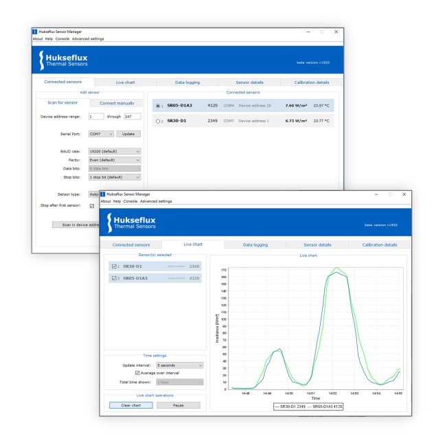
•    a thermal sensor with black coating. It has a flat spectrum covering the 200 to 50000 x 10⁻⁹ m range, and has a near-perfect directional response. The coating absorbs all solar radiation and, at the moment of absorption, converts it to heat. The heat flows through the sensor to the sensor body. The thermopile sensor generates a voltage output signal that is proportional to the solar irradiance.

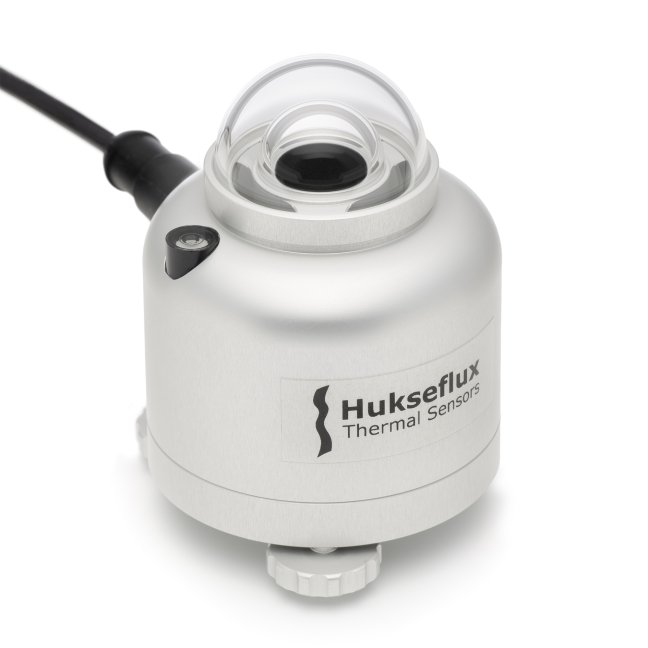
•    a glass dome. This dome limits the spectral range from 285 to 3000 x 10⁻⁹ m (cutting off the part above 3000 x 10⁻⁹ m), while preserving the 180 ° field of view angle. Another function of the dome is that it shields the thermopile sensor from the environment (convection, rain).

•    a second (inner) glass dome: For secondary standard and first class pyranometers, two domes are used, and not one single dome. This construction provides an additional "radiation shield", resulting in a better thermal equilibrium between the sensor and inner dome, compared to using a single dome. The effect of having a second dome is a strong reduction of instrument offsets.

•    a heater: in order to reduce the effect of dew deposition and frost on the outer dome surface, most advanced pyranometers have a built-in heater. The heater is coupled to the sensor body. Heating a pyranometer can generate additional irradiance offset signals, therefore it is recommended to activate the heater only during night-time. Combining a heater with external ventilation makes these heating offsets very low.

Why use a pyranometer?

There are good reasons why pyranometers are the standard for solar radiation measurement in outdoor PV system performance monitoring. 

The purpose of outdoor PV testing is to compare the available resource to system output and thus to determine efficiency. The efficiency estimate serves as an indication of overall performance and stability. It also serves as a reference for remote diagnostics and need for servicing.

The irradiance measurement for outdoor PV performance monitoring is usually carried out with pyranometers. Some standards suggest using PV reference cells. Reference cells are (with some minor exceptions) unsuitable for proof in bankability and in proof of PV system efficiency. Pyranometers are and will remain the standard for outdoor solar energy monitoring.

From a fundamental point of view:

  • Pyranometers measure truly available solar irradiance (so the amount of available resource). This is the parameter you need to have for a true efficiency calculation.
  • Reference cells measure only that part of solar radiation that can be used by cells of identical material and identical packaging (flat window), so the yield of a certain PV cell type. This is not a measurement that can be used in an efficiency calculation and in fact leads to several percentage points error in efficiency estimates.

The International Energy Agency (IEA) and ASTM standards for PV monitoring recommend pyranometers for outdoor PV monitoring. PV reference cells do not meet IEC 61724-1 class A requirements for irradiance measurement uncertainty: their directional response makes them systematically overestimate daily radiant exposure in J/m2 (or W·hr/m2 ) by more than 2 %, larger on hourly basis. 

How do I choose a pyranometer?

Choosing the right pyranometer for your application is not an easy task. We can offer assistance. But first, you should ask yourself the following questions:

  • are there standards for my application?
  • what level of accuracy do I need?
  • what will be the instrument maintenance level?
  • what are the interfacing possibilities?

When discussing with Hukseflux, our recommendation for the best suited pyranometer will be based on:

  • recommended pyranometer class
  • recommended maintenance level
  • estimate of the measurement accuracy
  • recommended calibration policy
  • recommended interface

Pyranometers can be manufactured to different specifications and with different levels of verification and characterisation during production. The ISO 9060 - 1990 standard, “Solar energy - specification and classification of instruments for measuring hemispherical solar and direct solar radiation”, distinguishes between 3 classes; secondary standard (highest accuracy), first class (second highest accuracy) and second class (third highest accuracy). From second class to first class and from first class to secondary standard, the achievable accuracy improves by a factor 2.

The ISO 9060 - 1990 standard is up for revision. The new 2018 version of the standard will be slightly different from the 1990 version. The new version of ISO 9060 includes three instrument accuracy classes A, B and C, and a special extension of every class “Spectrally Flat”, which is recommended for Plane of Array (POA), albedo, and reflected solar measurements.

Our pyranometer selection guide offers practical guidelines for choosing a pyranometer. The application of pyranometers in PV system performance monitoring according to IEC 61724-1 is highlighted as an example. Sensors specific for diffuse radiation and meteorological networks are also addressed in this selection guide.

What is the difference between a pyrheliometer and a pyranometer?

A pyranometer measures hemispherical solar radiation. When measuring in the horizontal plane this is called Global Horizontal Irradiance (GHI). When measuring in “plane of array”, next to PV panels, this is called plane of array POA irradiance.

A pyrheliometer is used to measure Direct Normal Irradiance (DNI). DNI is defined as the solar radiant flux collected by a plane unit surface normal to the axis pointing towards the centre of the sun, within an optical angular aperture. DNI is composed of the solar irradiance within the extent of the solar disk (half-angle 0.266 ° ± 1.7 %) plus some circumsolar radiation.

Hukseflux Sensor Manager
Hukseflux Sensor Manager software on a laptop for communication between a PC and digital Hukseflux pyranometers and pyrheliometers with a Modbus interface
  • provides a user interface for communication between a PC and digital Hukseflux pyranometers and pyrheliometers with a Modbus interface
  • allows the user to locate, configure and test one or more sensors and to perform simple laboratory measurements using a PC
Would you like a personalised quote?

or contact us: info@hukseflux.com