


How to calculate PV performance ratio and performance index
According to the latest IEC 61724 standard series
The IEC 61724 “Photovoltaic system performance” series of standards is the best available source that defines parameters such as “performance ratio” and “performance index”. The purpose of this document is to clarify the logic behind IEC 61724 and its vocabulary. For the sake of brevity we do not mention all parameters and performance metrics. If you want to know more: purchase the IEC standards.
Read the full article here: How to calculate PV power plant performance ratio and performance index - note (PDF)
Introduction
IEC has issued a series of 3 standards for PV system performance testing.
- IEC 61724-1, “monitoring” giving requirements for measuring. Revised in 2021
- IEC TS 61724-2 “capacity evaluation method” defining performance analysis based on the monitoring data over a short period of several sunny days, typically during commissioning and typically to verify if the system meets specifications. NOTE: This standard is under revision
- IEC TS 61724-3 “energy evaluation method” defining performance analysis based on the monitoring data over a long period of 1 year or longer than that. NOTE: This standard is under revision
Purpose of performance monitoring
IEC gives as possible purposes of PV performance monitoring:
- identification of performance trends in an individual PV system
- localization of faults in a PV system
- comparison of PV system performance to design expectations and guarantees
- comparison of PV systems of different configurations
- comparison of PV systems at different locations
Important factors in PV performance
The most significant and direct impacts on PV performance are:
- in-plane irradiance received by the PV array
- the PV cell temperature
- shading losses due to soiling or snow or row-to-row shading
Secondary factors that may enter the assessment are:
- clipping of the inverter, if the inverter cannot output more than a certain power in [W]
- curtailment; the network may not accept the available power
- losses (see next pages)
Performance model, ratio, index
IEC uses the following definitions:
- performance model gives a mathematical description of the electrical output of the PV system as a function of meteorological conditions, the system components, and the system design. This model is typically agreed upon in advance by the stakeholders of the test
- predicted output is the output for a given period as calculated using the performance model based on historical weather data
- expected output is the output calculated using the performance model when entering measured weather data
- measured output is the output measured at the power plant
- rating performance as specified by the manufacturer, usually confirmed via the name-plate on the panel, or as agreed upon by a supplier, typically under reference conditions such as STC Standard Test Conditions
- performance ratio (PR) is the ratio of measured output to expected output for a given reporting period based on the system name-plate rating
- performance index is the ratio of measured output to expected output for a given reporting period based on a more detailed model of system performance than the performance ratio
- PPI performance index based on power, Power Performance Index
- EPI performance index based on energy, Energy Performance Index
IEC 61724-1:2021
This standard outlines requirements for measuring equipment (sensors), methods, and terminology for performance monitoring and analysis of photovoltaic (PV) systems. In addition, it serves as a basis for other standards which rely upon the data collected, such as 61724-2 and 61724-3.
The standard defines 2 classifications of monitoring system, Class A and Class B. Class A systems are intended for high accuracy measurement at utility scale and large commercial PV systems.
The standard addresses sensors, installation, and accuracy for monitoring equipment in addition to measured parameter data acquisition and quality checks (system calibration and cleaning/maintenance), calculated parameters, and performance metrics.
For PV system performance assessment, electrical and environmental measurements are measured.
For Class A system monitoring stations, mandatory electrical measurements are:
- AC and DC output current
- AC and DC output voltage
- Active power
- Active energy
For Class A system monitoring stations, mandatory environmental measurements are:
- POA Plane of Array irradiance
- GHI Global Horizontal Irradiance
- Soiling ratio
- PV Module temperature
- Ambient air temperature
- Wind speed and direction
- PV module temperature (3 sensors per station)
Optional measurements are:
- Reflected or rear side solar irradiance
- Diffuse solar radiation
IEC TS 61724-2:2016
This standard defines a procedure for measuring and analysing the power [W] production of a photovoltaic system with the goal of evaluating the quality of the PV system performance.
It does so by comparing the measured power produced to the expected power, calculating the PPI, on a few relatively sunny days. The point of this test is that it can be done fast. The minimum test duration is 2 days, provided that these days meet certain boundary conditions. NOTE: the new draft of the standard proposes 3 to 5 days testing.
Class A monitoring systems must be used. Panels have to be “nominally clean”, operation has to be unconstrained (no clipping), the panels should be unshaded. Irradiance must be between pre-defined limits such as 0.5 to 1.2 TRC (Test Reference Condition) or for example above 500 W/m2. NOTE: new draft of this standard proposes 400 W/m2.
In this test, we accept a higher uncertainty than the test of IEC 71724-3. Hukseflux suggests working with irradiances of > 600 W/m2 only. The expected angle of incidence of the solar beam then is around 52 °, which is lower than the Brewster’s angle for glass, which is 56 °. Working at high angles of incidence reduces uncertainty due to the variation of reflectance, and reduces the uncertainty of the ratio between generated power and POA irradiance measurement.
A typical test outcome is a test report which includes a PPI involving a temperature correction and includes an expanded uncertainty.
IEC TS 61724-3:2016
This standard defines a procedure for measuring the energy [kWh] production of a photovoltaic system for comparison to expected electrical energy production, under actual weather- and other operating conditions over a year or more. A practical reporting period is 1 or multiple years.
The test offers a full assessment of electricity production. It covers all operating conditions, and offers insight in performance under all weather conditions, or times of the year. It also offers a picture of how other factors, such as maintenance, plant degradation and hardware failures impact the plant performance.
The expected electrical energy is calculated with a model; a simple temperature corrected PR can still have misleading variations due to seasonal effects and local conditions. More complex models, such as the Sandia PV Array Performance Model (SAPM), the System Advisor Model (SAM) and PVsyst, take into account measured weather conditions along with estimates for soiling and degradation.
In IEC 61724-3 the energy production is characterized separately for times when the system is operating (available) and times when the system is not operating (unavailable).
A typical test outcome is a set of performance indicators, most importantly a yearly “in service EPI” including an estimated expanded uncertainty.

Parameter definition in IEC
- in-plane irradiance Gi or POA: [W/m2] the sum of direct, diffuse, and ground-reflected irradiance incident upon an inclined surface parallel to the plane of the modules in the PV array, also known as plane-of-array (POA) irradiance (IEC 61724-1 3.13)
- Hi : [kWh/m2] in-plane irradiation
- EA : [kWh] Energy output from PV system (DC)
- Eout : [kWh] Energy output from PV system (AC), so after the inverter
- P0 : [kW] array power rating (DC) the total DC power output of all installed PV modules at the power rating reference condition, assumed to be standard test conditions (STC reference values irradiance 1 000 W/m2, at normal incidence, PV cell temperature 25 °C), typically as given on the name plate.
- P0, AC : [kW] array power rating (AC)
Yields and yield losses
Models and test reports may involve yields and losses. Calculation is covered by IEC 61724-1. Yields are ratios of an energy quantity to the array power rating P0. They indicate actual array operation relative to its rated capacity. Yields have units of [kWh/kW], where units of kWh in the numerator describe the energy output and units of kW in the denominator describe the system power rating. The yield ratio indicates the equivalent amount of time during which the array would be required to operate at P0 to provide the particular energy quantity measured during the reporting period.
- YA: [kWh/kW] PV array energy yield (DC per rated DC)
- Yf: [kWh/kW] final system yield (AC per rated DC)
- Yr : [kWh/kW] reference yield (DC)
Yield losses are calculated by subtracting yields. The yield losses also have units of [kWh/kW]. They represent the amount of time the array would be required to operate at its rated power P0 to provide for the respective losses during the reporting period.
- LC: [kWh/kW] array capture loss (Yr – YA)
- LBOS: [kWh/kW] balance of system (BOS) loss (YA – Yf)
Constrained operation
When output of inverters is limited below the maximum, we call this constrained operation.
In some cases, the operation of inverters is a bottleneck. They can only supply power within a certain range. If the power hits the upper limit of this range, we call this condition “clipping”.
If constrained, operation is caused by external factors, such as inability of the grid to receive the power. We call this “curtailment”. In case of clipping: consider reporting performance metrics based on Eout as well as EA.
Curtailment may involve periods of reduced grid/load demand or availability. The system generates power, but cannot supply it to the network. For purposes of performance assessments and performance guarantees, irradiation and yield sums should be calculated excluding such periods.
Traditional Performance Ratio
The Traditional Performance Ratio indicates the overall effect of losses on the system output and is the quotient of the system’s final yield Yf to its reference yield Yr
PR = Yf / Yr = (Eout / P0) / (Hi / Gi,ref )
Traditional PR neglects array temperature, typically resulting in seasonal variation.
Temperature-Corrected Performance Ratio
Seasonal variation of the traditional PR is removed by calculating a Temperature-Corrected Performance Ratio:
PR’ STC = (Eout / Ck P0) / (Hi / Gi,ref )
with
Ck = 1 + γ × (Tmod,k – Treference)
Using 25 °C as Tref gives PR’STC.
This term Ck corrects for difference between actual temperature and STC temperature used for power rating. The value of γ is usually negative and of the order of -0.3 %/K.
Module temperature is correlated with irradiance, so in case the performance is modelled; you must use a weighted average. PV panel temperature may rise up to 20 °C above ambient air temperature.
Annual Temperature-Corrected Performance Ratio
Approximates the value that would be obtained for traditional PR evaluated over one full year, by compensating for seasonal variation.
Digital twins
Analysis of PV system performance is increasingly based on modelling of the entire power plant using more complex models, such as the Sandia PV Array Performance Model (SAPM), the System Advisor Model (SAM) and PVsyst. These models no longer work with Gi (POA), but with GHI as input.
Critical measurements
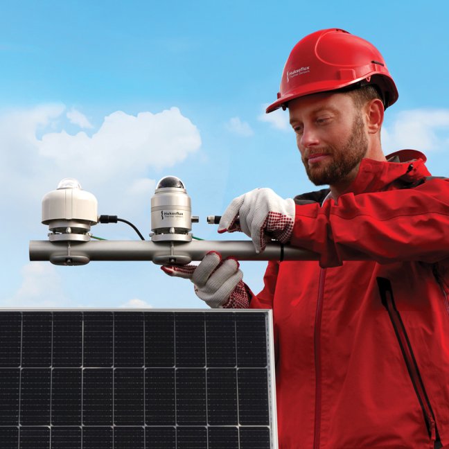
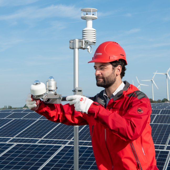
In PV system performance measurement, the most critical quantities are solar irradiance and PV module temperature. Here are some comments on the use of pyranometers and PV module temperature sensors.
Use of pyranometers
In PV system performance measurement, pyranometers are the instruments used to measure the solar irradiance. Systems were traditionally monofacial, and statically mounted at fixed tilt facing the equator. Measurement models were traditionally based on Plane of Array irradiance. With widespread use of single axis trackers (using backtracking so that there is no single Plane of Array), bifacial panels (also generating power from rear side irradiance), and installation on graded terrain, often global horizontal, reflected and diffuse irradiance measurements serve as input.
In Class A monitoring systems, the use of Class A pyranometers for GHI and POA is mandatory. Diffuse solar radiation measurement is optional.
IEC 61724-1 requires the use of ISO 9060 Class A pyranometers with dew and frost mitigation, for use in Class A monitoring systems, unless very little dew and frost are expected at the measurement site.
The Hukseflux pyranometer model SR30 complies with the requirements of Class A monitoring systems.
IEC 61724-2 recognises in 6.5.3 that special attention should be given to the irradiance data. It recommends performing a regular quality check using a comparison of multiple instruments on a clear day. In particular, false readings due to instrument shading should be removed from the dataset. At the location of all POA measurements, IEC 61724-3, clause 5 requires measurement of the local albedo to verify that it is representative of the albedo of the total power plant, and if it is within the range required for valid modelling. For monofacial modules, the albedo measurement is used in the uncertainty evaluation of the performance test.
In case bifacial modules are used, the rear side solar irradiance may
- be directly measured
- be estimated using an optical model from GHI, albedo, and optionally diffuse irradiance
The contribution of reflected radiation to the system performance is typically small. For measurement of reflected radiation, lower accuracy Class C pyranometers may be used.
IEC 61724-1 requires that pyranometers in Class A monitoring systems should be cleaned every week (unless it can be proven this is not necessary) and calibrated every 2 years.
Use of PV module temperature sensors
IEC 61724-2 (via Annex A) allows 2 methods to determine PV cell temperature:
- estimated, using a model, from measurement of POA irradiance. Ambient temperature, and wind speed
- from direct measurements using a PV module temperature sensor
The first method is not often used, because uncertainty of this model-based approach is relatively high.
Measurement of PV module temperature has a significant impact on the measured performance ratio. Users should carefully select and install such PV module temperature sensors. Poorly designed sensors will measure with a lower accuracy than the 2 ˚C required by IEC 61724-1.
IEC 61724-1 Annex B gives directions for temperature sensor installation. It is important to realise that sensors in general will measure a temperature between air temperature and panel temperature. Badly designed and badly installed sensors will measure a temperature that is too low. PV panels have temperature coefficients in the order of – 0.4 %/K; at lower a temperature we expect PV panels to perform better. A temperature-corrected estimate of PV system performance (performance index) using a sensor that measures a PV temperature that is too low, will result in a lower calculated level of performance; a lower performance index.
We expect that the absolute error in ˚C is proportional POA irradiance, so that the performance index is reduced by approximately the same percentage for all irradiance levels. At a lower measured PV panel temperature, we expect the PV system to perform better than it does in reality at its higher than measured temperature. In compliance testing or system commissioning this systematic measurement error or low estimate of the performance is a disadvantage for the seller.
Hukseflux supplies model PVMT01 PV module temperature sensor. This well designed sensor is expected to accurately measure the PV module temperature. PVMT01 fully complies with IEC requirements.
IEC 61724-1 requires a minimum of 3 such sensors for every monitoring station. A total of 6 or more sensors per PV system is required, depending on the size of the system.

Where can I order the standards?
The standards can be purchased from the IEC Webshop.
...
Read the full article here:
How to calculate PV power plant performance ratio and performance index - note (PDF)