What is a pyranometer?
A quick introduction to pyranometer basics
This article aims to give a reader with a basic level technical background an introduction to pyranometers and the measurement of global irradiances.

Read the full article here: What is a pyranometer - note (PDF)
Introduction to the pyranometer
Simply said a pyranometer is a device that measures solar irradiance from a hemispherical field of view incident on a flat surface. The SI units of irradiance are watts per square metre (W/m²).* Traditionally pyranometers were mainly used for climatological research and weather monitoring purposes, however recent worldwide interest in solar energy has also lead to an increased interest in pyranometers.
In this article we will explore the basic aspects of pyranometers: what does it measure; what is it useful for; and how does it work?
Pyranometer: a solar irradiance sensor
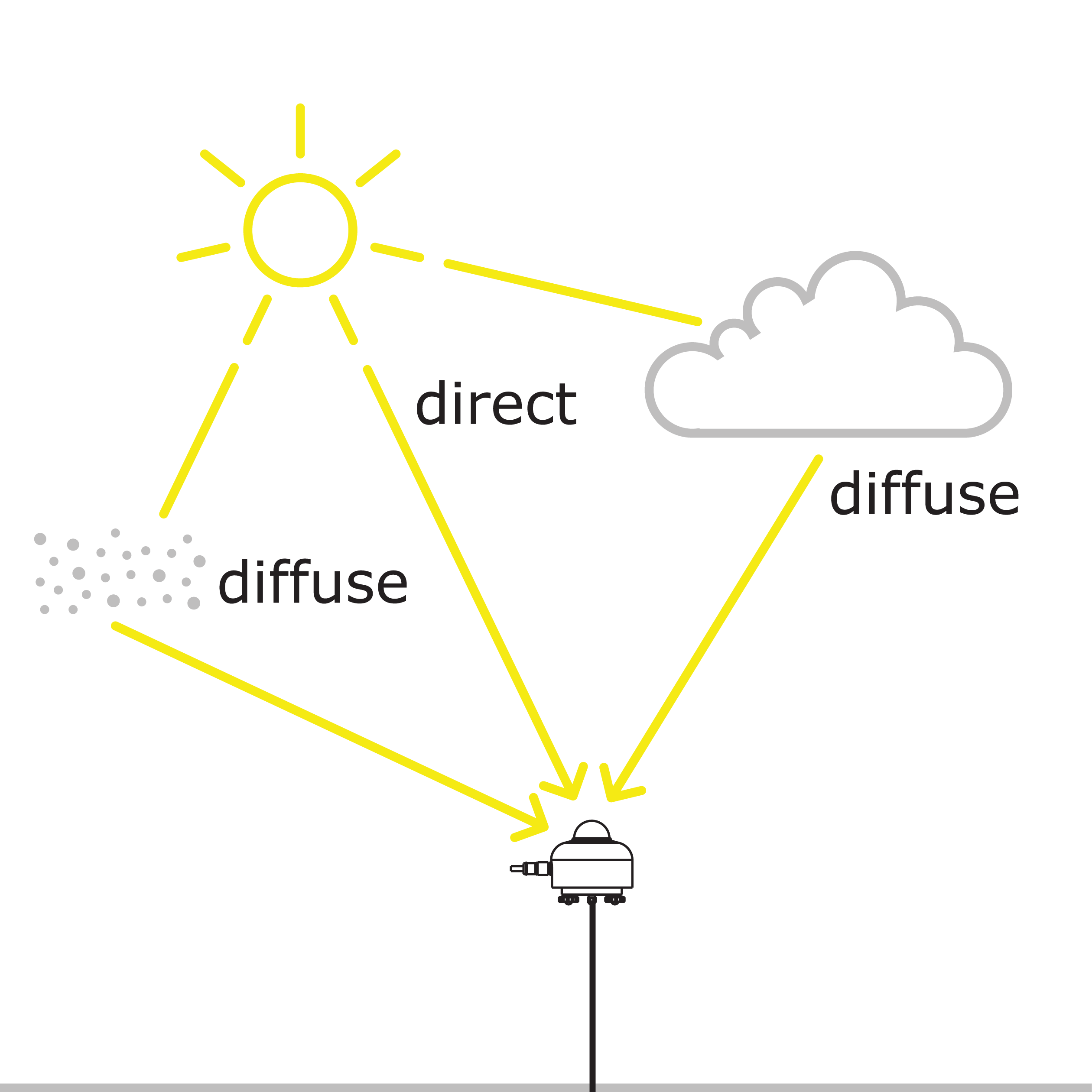
Pyranometers measure global irradiance: the amount of solar energy per unit area per unit time incident on a surface of specific orientation emanating from a hemispherical field of view (2π sr), denoted Eg↓. The global irradiance includes direct sunlight and diffuse sunlight, as illustrated in Figure 1. The contribution from direct sunlight is given by E⋅cos(θ) where θ is the angle between the surface normal and the position of the sun in the sky and E is the maximum amount of direct sunlight. The global irradiance is then:
Eg↓ = E⋅cos(θ) + Ed
where Ed accounts for the diffuse sunlight.

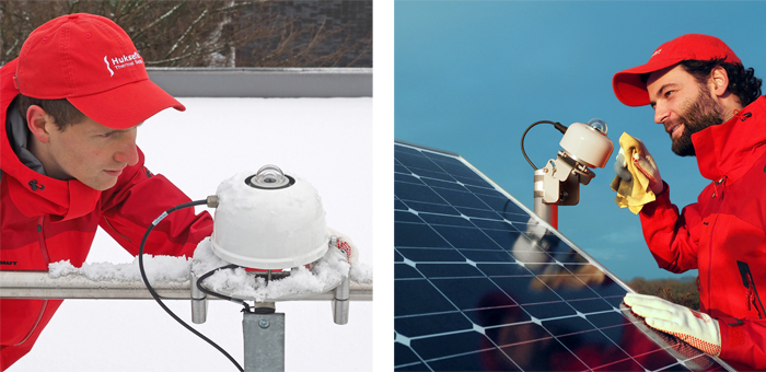
In many cases the surface of interest is horizontal such that the hemispherical field of view corresponds to the sky dome. In that case the measured quantity is the so called global horizontal irradiance (GHI) denoted Eg↓h (see Figure 2 left). In some cases the surface is tilted, for example in photovoltaic applications where the surface often corresponds to the plane of array (POA) of solar panels (see e.g. Figure 2 right). In this case the measured quantity is the global tilted irradiance (GTI) denoted Eg↓t.
A special case is the case were the surface is horizontal, but with the pyranometer facing downwards instead of towards the sky. In this case the measured quantity is the diffuse reflection from the surface of the earth, denoted Er↑.

The global irradiance may vary greatly depending on the height of the sun in the sky (and thus location on the earth, time of day and time of year) and on meteorological and environmental factors such as clouds, aerosols, smog, fog, precipitation and others. Typical values for the global horizontal irradiance are in the range from 0 to 1400 W/m². In some cases it can be larger for example due to reflections from buildings or snow or in a more exotic example at the centre of a solar concentrator.
What are pyranometers used for?
The sun is earth’s main source of extraterrestrial energy. This has important implications in two areas: weather and climate on the one hand and energy production by harvesting solar energy on the other hand.
Solar radiation is one of the driving forces behind the earth’s weather patterns and thus an important factor in weather and climate studies. In such studies pyranometers are mostly used to measure the GHI to determine the irradiance incident on the surface of the earth. The GHI that one would measure just outside earth’s atmosphere is fairly predictable, but at the surface of the earth the irradiance depends strongly on factors such as cloud coverage, aerosol concentration, fog and smog. Another interesting measurement is that of the net irradiance E*=Eg↓-Er↑ or the albedo A=Er↑/Eg↓. In this case two horizontally aligned pyranometers are used: one facing towards the ground and one facing towards the sky.
In the solar energy industry pyranometers are used to monitor the performance of photovoltaic (PV) power plants. By comparing the actual power output from the PV power plant to the expected output based on a pyranometer reading the efficiency of the PV power plant can be determined. Drops in efficiency may indicate that maintenance of the PV plant is required. Pyranometers can also be used to determine the suitability of potential sites for PV power plants. In this case pyranometers are used to determine the expected output of a PV installation.
Other areas of application also exist such as building automation or agriculture.
How does a pyranometer work?
Pyranometers are irradiance sensors that are based on the Seebeck- or thermoelectric effect. The main components of a pyranometer are one or two domes, a black absorber, a thermopile, the pyranometer body and in some cases additional electronics.
The dome on a pyranometer acts as a filter that transmits solar radiation with wavelengths from roughly 0.3 to about 3 x 10⁻⁶ m (this contains the near-infrared, visible, UV-A and part of the UV-B radiation, see Figure 3), but blocks thermal radiation with wavelengths longer than 3 μm. Occasionally a second dome is used to improve the pyranometer performance. Pyranometer domes are typically made from Schott N-BK7 glass or Schott WG295 glass, but in some cases sapphire or fused silica (Spectrosil or Infrasil) domes are used. The transmission τ of solar radiation through a dome is ideally close to 100 %, but is in practice closer to 92 %. The dome also serves to protect the black absorber and the thermopile from the elements (rain, snow, etc.).
The filtered radiation is absorbed by the black surface on the pyranometer and converted into heat. If the transmission through the dome(s) is τ, the area of the black surface is A and the absorption coefficient of the black surface is α then the heat absorption can be calculated as follows:
Pabsorption=α⋅τ⋅A⋅ Eg↓
This creates a temperature gradient from the black surface through the thermopile to the pyranometer body which acts as a heatsink. The temperature difference is given by:
ΔT=Rthermal⋅Pabsorption
Where Rthermal is the thermal resistance of the thermopile sensor. This thermal resistance depends on the specific composition and geometry of the thermopile sensor. A thermopile consists of a number of thermocouples connected in series. Each thermocouple will generate a voltage proportional to the temperature difference between the black surface and the body:
u = ς⋅ΔT
Where ς is the Seebeck coefficient. For example, the Seebeck coefficient of a copper-constantan thermocouple is 41 x 10⁻⁶ V/K.
Pyranometer specifications
Each pyranometer can have different specifications. Below you will find more information about the classification of these sensors and about the topic "spectrally flat".
Classification
Depending on the pyranometer specifications such as the response time, thermal offsets, non-stability, non-linearity, directional response, spectral response, temperature response and tilt response; and on the calibration method, a pyranometer may be classified either as a Class A, Class B or Class C pyranometer in accordance with the ISO 9060 standard.
A more in-depth discussion on how pyranometers work can be found in the book by Vignola et al.⁴
Spectrally flat
ISO 9060 defines pyranometer classes A, B and C. The standard also adds a new subclass, called "spectrally flat".
The vast majority of users needs to use instruments of the spectrally flat subclass; only spectrally flat instruments measure with high accuracy, also when a cloud obscures the sun, or when the irradiance includes reflected radiation. These situations occur for example when you measure Global Horizontal irradiance (GHI) under partly or fully cloudy skies, when you meaure Plane of Array (POA), albedo or net-radiation. Normal instruments, just of class A, B or C, and not spectrally flat, only measure accurately under clear sunny skies.
Using "spectrally flat" instruments is easy because this ensures: you can measure accurately not only horizontally under clear-blue-sky but also general GHI, POA, albedo and net radiation using the same instrument with the same calibration.
...
Read the full article here: What is a pyranometer - note (PDF)
View all pyranometers.


