


How to measure heat flux?
Heat flux is the energy flux onto or through an object. It is essential to know the heat flux of an object if you want to fully describe its thermal condition. The transport of heat can occur in three ways:
- Conduction
- Convection
- Radiation
Measuring these three different types of heat flux can be done with different types of heat flux sensors and accessories. The type of sensor depends on, among other things, flux level or temperature.

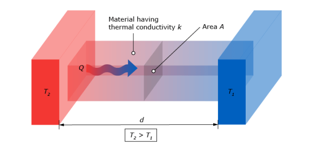
The conductive heat flux is driven by the temperature difference between the hotter end of an object and the colder side. When a heat flux sensor is placed in the object, the conductive heat will flow from the hot side through the sensor to the cold side of the object.
The working principle of heat flux sensors is based on the thermoelectric effect. A thermopile converts the temperature difference between the object and the surroundings into a small voltage. This voltage is the output of the sensor and is proportional to the local heat flux.
Introduction to thermopiles
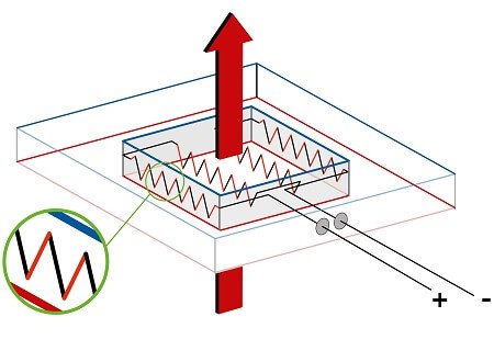
The thermopile inside a heat flux sensor converts a temperature difference into a small voltage, an electric signal. This is a passive process, meaning that the thermopile does not need to be powered. A thermopile is a string of thermocouples. To understand how a thermopile works, we must first look at a single thermocouple.
A thermocouple consists of two electrically conducting, dissimilar metals. When an electrically conducting metal is exposed to a temperature difference, a small voltage is generated through the material. This is called ‘the thermoelectric effect’ or ‘Seebeck effect’. The output voltage level that is generated depends on the material and on the temperature difference, as described below:
![]()
With: ![]() = Generated Voltage [V].
= Generated Voltage [V].
S = Seebeck coefficient of a particular metal [V/K]. ![]() T = Temperature difference [K].
T = Temperature difference [K].
Every metal has a different Seebeck coefficient, “S”. A thermocouple takes advantage of this property by connecting two ends of two different kinds of metal wires and thus creating a potential difference. This potential difference is in the millivolt range.
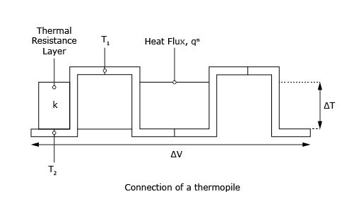
These wires run back and forth across the temperature difference, from cold to hot and back. Starting on the cold side, the first metal type extends to the hot side. At the hot side, the wire of metal type 2 is attached. This wire runs back to the cold side.
Because of the different Seebeck Coefficients of the two metals, a net voltage is created over the thermocouple. The resulting voltage is calculated with:
![]()
When the Seebeck coefficients of both metals are known, and the generated voltage is measured, we can calculate the temperature difference between the hot and the cold side.
To do this calculation, the generated millivoltage must be measured very accurately. This can be a challenge to measure. By connecting multiple thermocouples we can amplify the voltage, creating a thermopile.
As said before, a thermopile is essentially a large quantity of thermocouples placed in series. The voltage generated over a thermopile is the sum of the voltages generated by all individual thermocouples. That leaves the expression:
![]()
With:
N = The number of thermocouples inside the thermopile.
This amplified voltage can be measured accurately. With the help of the sensitivity of the sensor, the heat flux can be determined. The known voltage is proportional to the temperature difference. Heat flux sensors are calibrated by exposing them to a known heat flux. The voltage output divided by the known heat flux is the sensitivity.
Heat flux is further explained in the article: What is heat flux?
Considerations before heat flux measurement
Before you can start your heat flux measurements, some things should be considered. The first question you have to answer is: What is it you want to measure? The type of heat flux you want to measure is critical for choosing a heat flux sensor. Consider in what conditions the sensor, or sensors, should be operating. The following points are important to consider:
- Operating temperature range is important as some sensors are more heat resistant
- The range of heat flux wanted to be measured
- The sensitivity you want your measurements to have
- The response time
- Chemical resistance and other safety requirements dependent on location
- Size, shape and flexibility of the sensor
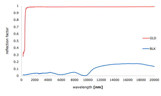
- Spectral properties of the sensor. These properties dictate the rate at which the sensor emits radiation
Choosing and installing the right heat flux sensor
Hukseflux is the market leader in heat flux measurement. We offer a wide range of sensors for measuring heat flux in many applications. Different heat fluxes and different environments require different types of sensors to ensure accurate and reliable measurements. For instance, the FHF05-15X85 model is specifically designed for measuring at curved surfaces like pipes or tubes. The water-cooled GG01 is designed for high, industrial measurements up to 200 × 103 W/m2. The IHF02 is an extremely sensitive heat flux sensor designed to measure the smallest heat fluxes accurately at high temperatures in an industrial setting. Our BLK-GLD sticker series can be used to measure convective and radiative heat flux separately.
For more information on our available products and their applications please visit our webpage with all heat flux sensors.
The don'ts of thermal sensors
There are a few things to be aware of when installing a heat flux sensor. The following properties of heat flux measurement systems are unwanted and should be avoided:
- Too small a sensor for the application. Use multiple sensors to average out the heat flux.
- Vulnerable wiring. Make sure that the wires attached to the sensor have strain relief to prevent damages to the wires and connections.
- Air cavities. Some designs use air cavities in the sensor. They may fill up with water and cause internal corrosion.
- Seeing the thermopile pattern directly. If you can see the previously described pattern of the thermopile, it means the sensor has no spreader. Spreaders help reduce the thermal conductivity dependence of the measurement.
- No thermal guard. Watch out for edge effects, these occur when the thermal spreader extends over the entire sensor up to the edges. Thermal spreaders are often a good idea, but only when used correctly.
Heat flux measurement video
If you would like to know more about heat flux measurement, you can watch our video that explains what heat flux is and how you can measure heat flux.
Related to How to measure heat flux?
Heat flux sensors: the latest technologies