


Heat flux sensor technology: why use sensors with low thermal resistance and with spreaders
Heat flux sensor technology review
Heat flux measurement is not easy. On a macroscopic level: the presence of a sensor potentially affects the local heat flux. For a representative measurement: use a sensor with a low thermal resistance. Also, the environment of the sensor - the thermal conductivity of the surrounding material - acting at a microscopic level, potentially affects the sensitivity of heat flux sensors. This is why Hukseflux sensors have “spreaders”; thin metal foils covering the thermopile, creating an environment for the internal thermopile sensor that does not depend on the way it is installed. Tests* confirm superior performance.
* Experiments were carried out on Hukseflux HFP01 and FHF05-50X50 models, as well as sensors purchased from a leading supplier of printed heat flux sensors with thermopiles based on electrically conductive inks, and a sensor model employing a semiconductor thermopile. The test results may not be applicable to sensors produced by other manufacturers or when improving manufacturing technology.
Read the full article here: Heat flux sensor technology review - why use sensors with spreaders (PDF)
Heat flux sensors
Heat flux sensors measure a temperature difference across a thin layer of material. They typically employ a thermopile, which is manufactured by creating an alternating pattern of two dissimilar conductors, generally metal alloys. See Figure 2.
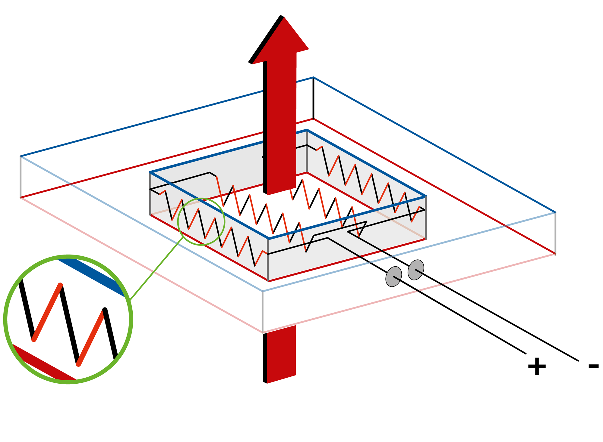
Figure 2 Heat flux sensor principle: the sensor contains a thermopile consisting of an alternating pattern of two metal alloys.
Macroscopy: thermal resistance
On a macroscopic level: a heat flux sensor has a certain thermal resistance.
- mounted on a surface, the sensor always represents an additional resistance
- surrounded by a material, the sensor may locally increase or decrease thermal resistance
Users should ask themselves what consequences this has for their measurement.
To avoid making measurement errors due to thermal resistance, Hukseflux takes the following countermeasures:
- use high-thermal-conductivity materials (HFP01 ceramics-plastic composite)
- use thin sensors (FHF series)
- use guards, i.e. non-sensitive parts around a central heat flux sensor, so that sensors do not measure at the edges, where measurement errors are the highest (HFP01 and FHF05 series)
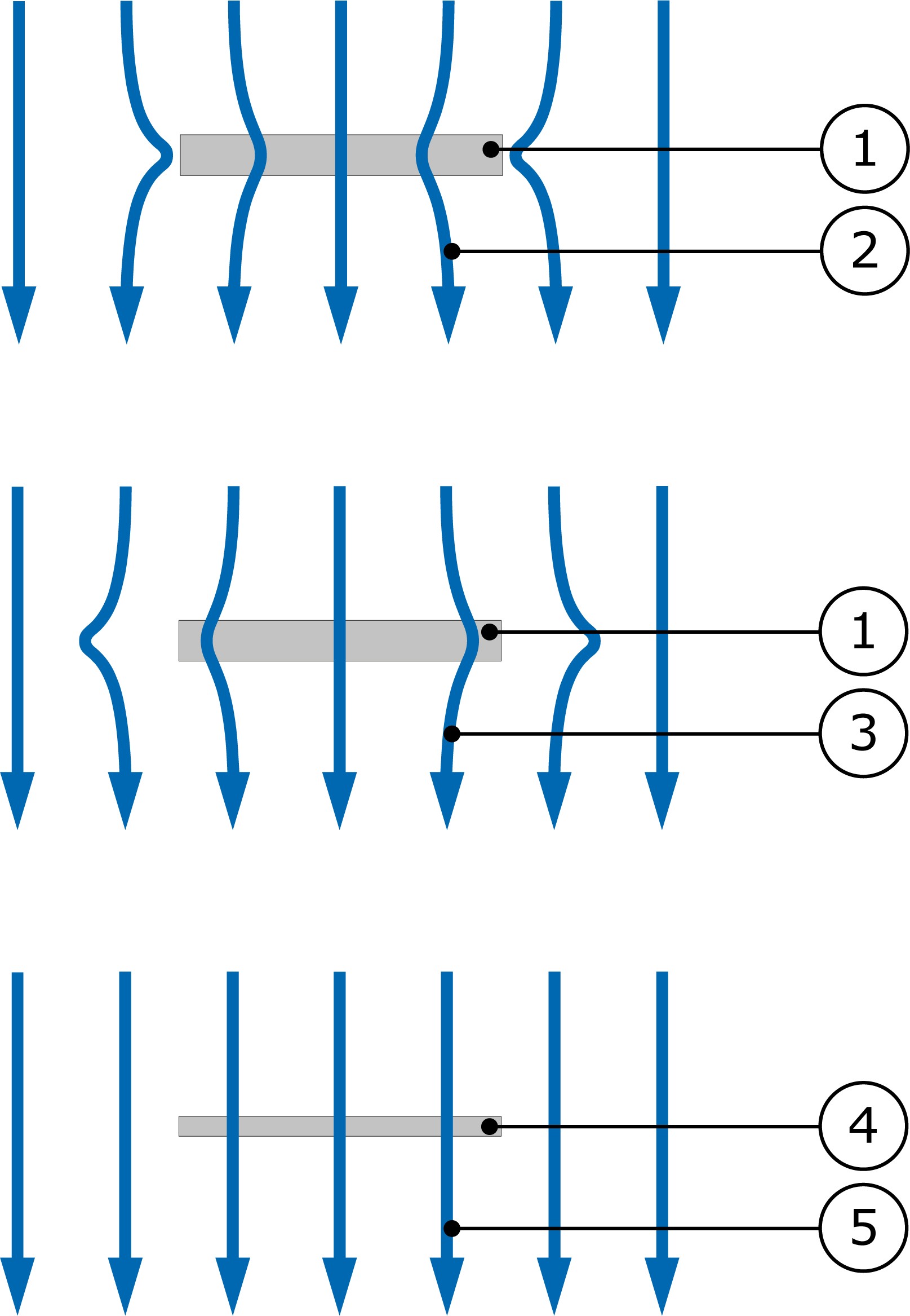
Figure 3 Macroscopic view of a heat flux sensor (1), in a heat flux field (2). Upper picture showing a sensor that has a higher thermal conductivity than its environment. Heat then tends to flow towards the sensor. The measurement result is an overestimation of the actual (undisturbed) heat flux. The centre picture shows a sensor (1) with a lower thermal conductivity then its environment. Heat flux (3) at the point of measurement (centre of sensor) is lower than in the undisturbed situation. The bottom picture shows a relatively thin and well conducting sensor (4), leading to an almost undisturbed heat flux and small measurement error.
Microscopy: spreaders and thermal conductivity dependence
Inside a heat flux sensor, you will find a thermopile, typically embedded in plastic material, see Figure 2. The traces of the thermopile are electrical conductors, which typically will also conduct heat quite well. Seen from the outside, a sensor may look like “A” in Figure 5. “Spreaders” are thin metal foils covering the thermopile. There may be one large spreader as in “B”, or multiple small spreaders like “C”. To explain the benefits of using spreaders, we zoom in on the sensor as in Figure 4, and focus on microscopic effects:
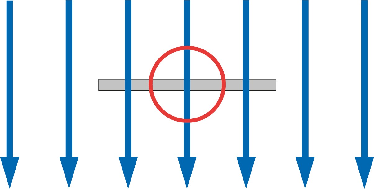
Figure 4 To explain microscopic effect we zoom in on a section of the heat flux sensor. This detail can be seen in Figure 7.
We make a distinction as in Figure 5:
- A: a sensor without a spreader; the thermopile may be visible and is directly exposed
- B: sensors with a single large spreader of well conducting metal foil. (applied in Hukseflux models HFP01)
- C: sensors with multiple small spreaders (applied in all Hukseflux models of FHF05 series and FHF06)
In Figure 7 you can see what happens at a microscopic level to the heat flux:
- A1: a sensor without a spreader surrounded by a material with high thermal conductivity will measure a heat flux that is too high; the path of least resistance for heat is through the metal thermopile materials. The high thermal conductivity of the surrounding material offers a relatively easy path sideways, and the thermopile is exposed to a relatively high flux.
- A2: a sensor without a spreader surrounded by a material with low thermal conductivity will measure a heat flux that is too low
- B, C: in sensors with a single spreader or multiple small spreaders, the thermopile sensor is always exposed to the same environment i.e. the spreader. Heat arriving from outside the sensor there is no path of least thermal resistance.
The result is that sensor model A will have a sensitivity that depends on the thermal conductivity of the surrounding material.
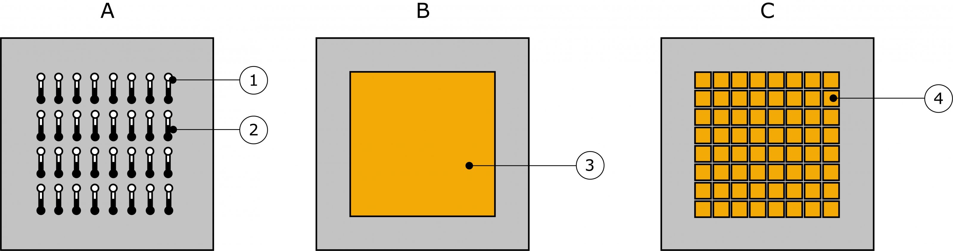
Figure 5 A: sensor without a spreader. One thermopile alloy (1), other thermopile alloy (2) In B and C, the thermopile is covered by spreaders. B: sensor with a single large spreader (3) C: sensor with multiple small spreaders (4).
Thermal conductivity dependence
Thermal conductivity dependence is an intrinsic property of a heat flux sensor that its sensitivity depends on the thermal conductivity of the surrounding material. This is expressed as % change of sensitivity, either absolute or per [W/(m·K)] change of thermal conductivity. Thermal conductivity dependence is reported relative to the sensitivity at the calibration reference condition, mounted on a metal heat sink. There are no standardised experiments to perform tests. The results presented are therefore “comparative” only.
Test results
The sensitivities of the sensors were tested under different conditions. The reference condition is mounted on aluminium, the other conditions surrounded by Pyrex (glass) and silicone (plastic) create an environment with different thermal conductivities.
Of sensor type A (Figure 5), thermopiles made with two different manufacturing techniques from leading suppliers were tested: the first based on electrically conductive inks and the second based on semiconductor materials. Test results are presented in Figure 6. When determining the sensitivity, the capability to measure changes has a reproducibility in the order of 1 %, asserting that changes of 3 % can meaningfully be detected. In this experiment the calibration uncertainty is set at ± 5 %.
Test results show a very significant thermal conductivity dependence of sensors of type A, while the error types B and C are much smaller than the calibration uncertainty.
Conclusions
- when used under conditions different from the calibration reference conditions (conditions for which the calibration is valid) heat flux sensors without spreaders may make large measurement errors because of their thermal conductivity dependence.
- use of sensors with spreaders, reduces this risk. Measurement errors become negligible.
Discussion
Sensors with spreaders of type B and type C such as the FHF series supplied by Hukseflux, have a negligible thermal conductivity dependence. By contrast, type A sensors produce large errors when used in an environment different from the one in which it was calibrated.
Read the full article here: Heat flux sensor technology review - why use sensors with spreaders (PDF)