


Insulation measurement with 2 thermocouples and a heat flux sensor
The following article describes the concept of insulation and a way to measure insulation. An important distinction to be made is that this article only regards thermal insulation, not electrical insulation.
What is insulation?
Insulation is a term used to describe the amount of effort that it takes for thermal energy to traverse through a substance. It could also be described as the result of the thermal resistance of an object. A heavily insulated object has a high thermal resistance, resulting in a relatively small flow of thermal energy, flowing from hot to cold. This flow of thermal energy is called ‘heat flux’.
Usually, insulation regards the conductive heat flux. An insulated material is not conductive, having a high thermal resistance. But insulation can also influence the convective and the radiative heat flux of an object. For instance, a very well-known type of insulation is a persons clothes. By adding a thin layer of non-conductive material (cotton for example), a person can keep warm more easily. How this physical phenomenon works is further explained below. If you are not yet familiar with the concepts of the three types of heat flux (conduction, convection and radiation), please read the following article: What is heat flux?

Applications of insulation
Insulation is a very common phenomenon. For instance, buildings are depending on insulation for keeping their energy consumption low. As insulation blocks the flow of heat, it is very useful for regulating temperatures.
In the winter, when it is cold outside of a building, good insulation saves energy to keep the warmth inside. This way less heating is needed to maintain a certain temperature. In summer, when it is hot outside, good insulation prevents needing air conditioning to keep a low temperature. Good insulation is attained by placing double glass, sealing off small cracks in the building and using insulating materials in the walls and floors.
Not only clothes and buildings, but also a lot of household items are designed to be insulating. Pots and pans often have a wooden handle, blocking the conductive heat flux of the hot pan from flowing into your hand, preventing a burn. Ovens, fridges and freezers are heavily insulated to keep their desired temperatures with as little effort as possible.
Physics of insulation
So in short, insulation prevents heat from flowing. In other words, it lowers the incoming and outgoing heat flux of an object. The total incoming and outgoing heat flux of an object is described by their three components: conduction, convection and radiation. Insulation effects each of these components differently, as explained below.
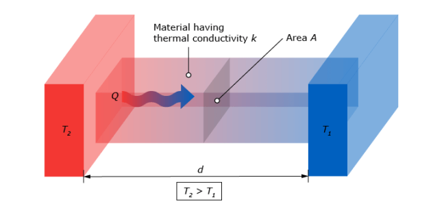
- Conduction. This type of heat flux regards the thermal energy traveling through solid materials. The formula for the conductive heat flux of an object is:
With:
q(x) = Conductive heat flux per unit of area at place x. [W/m2]
k = thermal conductivity of material. [W/mK] ![]() = T2 – T1. Difference between temperatures at place x1 and x2. [K]
= T2 – T1. Difference between temperatures at place x1 and x2. [K]
![]() = x2 – x1. Distance between location of T1 and T2. [m]
= x2 – x1. Distance between location of T1 and T2. [m]
Notice that the conductive heat flux, q(x), is expressed in W/m2. To attain the total conductive heat flux of an object, this value should be multiplied with its corresponding area.
The coefficient k, the thermal conductivity, is an inherent property of a material. An insulating material has a very low thermal conductivity, resulting in a very low conductive heat flux.
- Convection. This type of heat flux regards thermal energy exchanges between a solid and a fluid, or between two fluids. The expression for convective heat flux is:
![]()
With:
q = Convective heat flux per unit of area. [W/m2]
hc = convective heat transfer coefficient, a coefficient for the rate of convection,
different for every particular system. [W/m2K] ![]() = The difference in temperature of the solid and the fluid. [K]
= The difference in temperature of the solid and the fluid. [K]
Again, the heat flux is expressed in W/m2 thus for the total convective heat flux, it should be multiplied with its corresponding area.
The convective heat flux of an object can be reduced by dividing large volumes of the fluid into smaller pockets. Styrofoam is a good example of this concept. The material Styrofoam consists approximately 90-95 percent of air. Because the air can’t move around, the material is considered a solid. The convective heat transfer coefficient for air is around 2.5 – 25 W/m2K while the thermal conductivity coefficient of Styrofoam is 0.04 W/mK. Styrofoam is known to be a great insulator.
Even though over 90 percent of Styrofoam consists of air, both ‘materials’ behave completely different when it comes to the transfer of thermal energy.
- Radiation. The third type of heat flux is thermal radiation. Every object with a temperature emits radiation to a certain degree, dependent on its surroundings. The amount of radiation emitted by ‘object 1’ and arriving at ‘object 2’, is expressed as follows:
![]()
With: ![]() = radiative heat flux from body 1 to 2. [W]
= radiative heat flux from body 1 to 2. [W] ![]() = The transfer factor from body 1 to 2. [-]
= The transfer factor from body 1 to 2. [-] ![]() = The radiative surface of body 1. [m2]
= The radiative surface of body 1. [m2] ![]() = Stefan-Boltzmann constant of 5.67 * 10-8. [W/m2K4]
= Stefan-Boltzmann constant of 5.67 * 10-8. [W/m2K4]
T1 = Temperature of body 1 at the surface. [K]
T2 = Temperature of body 2 at the surface. [K]
An important notion is that the temperature is raised to the fourth power. That means that the amount of radiation that an object emits will grow exponentially with respect to its temperature.
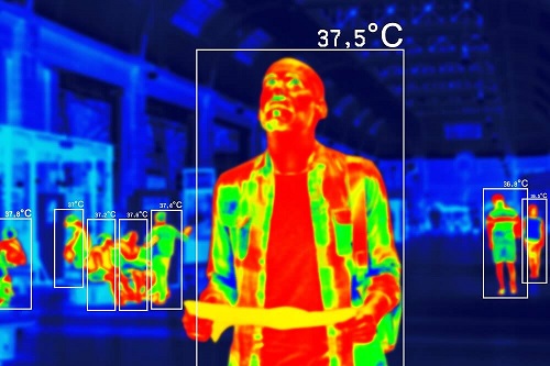
To prevent a person's body from radiating a lot of energy to its surroundings, a layer of clothing helps a great deal. The following figure depicts the thermal image of a clothed man. The body of this man radiates thermal energy onto his clothes. The clothes absorb this radiation and emits it in two directions. Half of the radiation is sent back to the man and the other half radiates outward to his surroundings. The clothes represent a simplified version of what clouds are to the greenhouse-effect.
The thermal image clearly shows that the clothes are emitting a smaller amount of radiation to the surroundings than the man's skin. By the law of conservation of energy, less radiation to the surroundings must mean that the man is absorbing his own radiation indirectly. This causes the clothed parts of his body to feel warmer. This type of insulation can also be applied for animals, buildings, and even plants.
How to calculate insulation or thermal resistance
Now that the concept of heat flux and the physics of insulation have been explained, it is only reasonable to want to measure these phenomena.
As insulation can influence all three types of incoming and outgoing heat flux, calculating this heat flux can be very complicated. For the sake of simplicity, a flat wall is used here as an example.
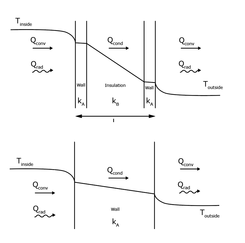
Situation 1 describes the heat flux of a standard wall. Situation 2 describes the heat flux of an insulated wall. Because heat flux always flows from hot to cold, the heat is going from left to right. Firstly, the warm air inside transfers heat to the wall by convection. Secondly, the thermal energy dissipates through the wall by conduction, before reaching the outer surface. Here, thermal energy escapes the face of the wall by both convection and radiation, warming the surroundings outside.
The main difference between the two images is the insulation in the second image. This insulation has a very low conductivity, kB. This low conductivity, or high thermal resistance, preserves the temperature from the inside better than the standard wall material. The insulation material resists the flow of thermal energy, making sure it does not dissipate to the outside (as much).
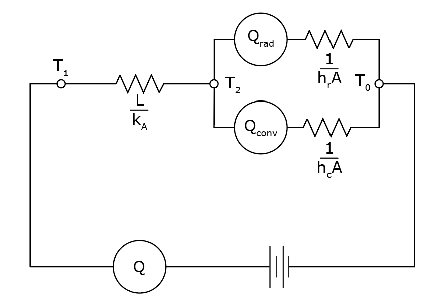
To calculate the amount of heat flux exiting the wall, the conductivities of both materials have to be known, the temperature difference between the outside and inside has to be known, the convective heat transfer coefficients have to be known and the transfer factor from the wall to the outside have to be known.
These types of math problems are very common and are often represented as electrical circuits like the one below. These circuits can represent many problems regarding heat flux because the physics of ‘potential’, ‘resistance’ and ‘flow’ are fundamental to both teachings.
Measuring insulation with 2 thermocouples and a heat flux sensor
Very often, the process of making digital models of objects with incoming and outgoing heat fluxes is too complicated. Every different object, form and material has six differential equations of which two are non-linear. Because of this complexity, many models are simplified. This simplification makes the calculations easier but also less reliable. For this reason, being unable to calculate your answer, you can measure it.
The first decision to make is about what you want to measure. It is important to understand the difference between heat flux, temperature, conductivity and thermal resistance. Let’s say you want to know the insulative properties of a material. If you know the conductivity of a material, you have a good idea if it is a good insulation material. Measuring the conductivity of a material can easily be done if you have right equipment.
At Hukseflux thermal sensors we provide a thermal conductivity measuring system, called: TRSYS20. This thermal conductivity measuring system consist of multiple heat flux- and temperature sensors that are used to measure heat fluxes through- and temperature difference across walls or building envelope components. The data can be used to estimate the energy budget of buildings and to determine thermal resistance of walls.
TRSYS20 uses HFP01 heat flux sensors to measure the heat flux through a particular material, measured in W/m2. The HFP01 heat flux sensors, also a product of Hukseflux thermal sensors, contain a thermopile that generates an output voltage proportional to the temperature difference across the measured material. If you want to learn more about how a thermopile converts a temperature difference into an output voltage, please read the article: How to measure heat flux?
To measure the temperature difference, TRSYS20 uses two thermocouples positioned on both ends of the material. If the pairing of the thermocouples is done correctly the uncertainty in temperature difference is smaller than 0.1 °C.
The measurement and control unit, or ‘MCU’, is used to measure the voltage signals from the heat flux sensors. The MCU processes the signals, stores the measurements and makes them easily accessible and interpretable for the user. Furthermore, the MCU contains an internal clock and memory. Every 10 minutes the average heat flux, temperature and temperature differences are stored along with corresponding time stamps. All this data is easily found in the interface of TRSYS20 via a laptop with an internet browser.